2004 Jeep Grand Cherokee 4.7 Blower Fuse Diagram
Fuse box diagram (fuse layout), location, and assignment of fuses and relays Jeep Grand Cherokee (WJ) (1999, 2000, 2001, 2002, 2003, 2004, 2005).
Checking and Replacing Fuses
A fuse is an element for protecting the electrical system. A fuse will trip (i.e. it will blow) in the event of a failure or improper interventions in the electrical system.
If an electrical device is not working, check whether the respective fuse is blown. Look at the silver-colored band inside the fuse. If the band is broken or melted, replace the fuse. Check those fuses first that protect the failed component, but check all the fuses before deciding that a blown fuse is not the cause. Replace any blown fuses with another with the same amperage (same color) and check the component's operation.
Notice
- Before changing a fuse, check the ignition key has been removed and that all the other electric devices have been turned off/disabled.
- Never replace a broken fuse with anything other than a new fuse. Always use a fuse of the same color.
- Never change a fuse with another amperage. This can cause damage to the electrical system and fire.
- If the fuse blows again, have the vehicle inspected at a qualified service center.
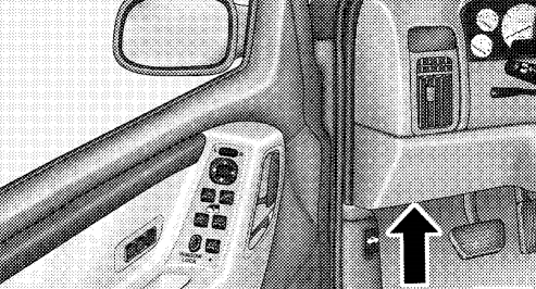
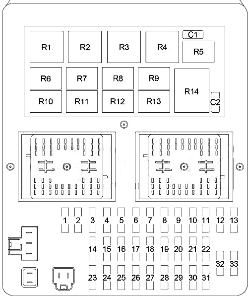
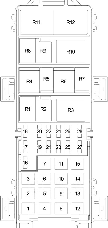
Passenger Compartment Fuse Box
The interior fuse panel is on the lower instrument panel just to the left of the steering column. A label is stamped on the fuse panel cover to identify each fuse for ease of replacement.
| № | A | Protected Component |
|---|---|---|
| 1 | - | - |
| 2 | - | - |
| 3 | 10 | Left Headlamp (High Beam) |
| 4 | 15 | Combination Flasher |
| 5 | 25 | Radio, Amplifier |
| 6 | 15 | Park Lamp Relay (Park Lamp, Tail Lamp, License Lamp, Trailer Tow Connector, Headlamp Leveling Switch) |
| 7 | 10 | Body Control Module, Underhood Lamp, Sentry Key Immobilizer Module, Automatic Zone Control Module, Automatic Headlamp Light Sensor/VTSS LED, Remote Keyless Module |
| 8 | 15 | Rear Wiper Motor, Courtesy Lamp, Glove Box Lamp, Cargo Lamp, Overhead Map Lamp, Door Handle Lamp, Vehicle Information Center, Liftgate Flip-Up Push Button Switch, Security System Module, Visor/Vanity Lamp |
| 9 | 20 | Front Power Outlet, Rear Power Outlet, Power Connector |
| 10 | 20 | Adjustable Pedals (?-2004) |
| 11 | 10 | Automatic Zone Control Module (AZC), Manual Temperature Control (MTC) |
| 12 | 10 | Fuel Pump Relay, Automatic Shut Down Relay, Powertrain Control Module, Transmission Control Relay (4.7L) |
| 13 | - | - |
| 14 | 10 | Left Headlamp (Low Beam) |
| 15 | 10 | Right Headlamp (Low Beam) |
| 16 | 10 | Right Headlamp (High Beam) |
| 17 | 10 | Data Link Connector, Instrument Cluster |
| 18 | 20 | Trailer Tow Brake Lamp Relay, Electric Brake (1999-2001-?) |
| 30 | Trailer Tow Brake Lamp Relay, Electric Brake (?-2004) | |
| 19 | 10 | ABS |
| 20 | 10 | Combination Flasher, Automatic Zone Control Module (AZC), Manual Temperature Control (MTC), Temperature Valve Actuator (MTC), Transmission Solenoid/TRS Assembly (4.7L), Park/Neutral Position Switch (4.0L, 3.1L TD), Driver/Passenger Heated Seat Switch |
| 21 | 10 | Gasoline: Air Conditioner Compressor Clutch Relay, EVAP/Purge Solenoid, Brake Transmission Shift Interlock Solenoid |
| 10 | Diesel: Fuel Heater Relay, Engine Control Module, Brake Transmission Shift Interlock Solenoid | |
| 22 | 10 | Body Control Module, Instrumeent Cluster, Sentry Key Immobilizer Module, Vehicle Information Center, Automatic Day/Night Mirror, Security System Module |
| 23 | 15 | Stop Lamp Switch |
| 24 | 15 | Front Fog Lamp Relay, Body Control Module |
| 25 | 20 | Sunroof Delay Relay, Body Control Module |
| 26 | 15 | Cigar Lighter |
| 27 | 15 | Rear Fog Lamp Relay |
| 28 | 10 | Body Control Module |
| 29 | 10 | Cigar Lighter Relay, Right Multi-Function Switch |
| 30 | 15 | Radio |
| 31 | 10 | Starter Relay, Transmission Control Module (4.7L) |
| 32 | 10 | Airbag Control Module |
| 33 | 10 | Airbag Control Module |
| | ||
| C1 | 20 | Front Wiper Motor, Wiper (On/Off) Relay (Wiper (High/Low) Relay) |
| C2 | 20 | Power Seat |
| | ||
| R1 | Low Beam / Daytime Running Lamp | |
| R2 | Cigar Lighter | |
| R3 | Combination Flasher | |
| R4 | Rear Window Defogger | |
| R5 | Rear Fog Lamp | |
| R6 | Low Beam | |
| R7 | High Beam | |
| R8 | Sunroof Delay | |
| R9 | - | |
| R10 | Front Fog Lamp | |
| R11 | - | |
| R12 | Park Lamp | |
| R13 | - | |
| R14 | - | |
Engine Compartment Fuse Box
Your vehicle is equipped with an electrical power distribution center located in the engine compartment near the battery.
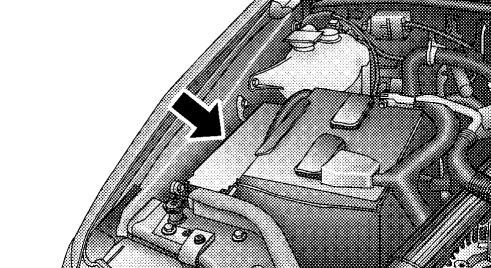
This power center houses plug-in "Cartridge" fuses which replace in-line fusible links. The power center also contains "Mini" fuses and plug-in full and mini ISO relays. A label inside the latching cover of the center identifies each component for ease of replacement, if necessary. "Cartridge" fuses and relays can be obtained from your authorized dealer.
| № | A | Protected Component |
|---|---|---|
| 1 | 40 | Blower Motor (MTC), Blower Motor Controller (AZC) |
| 2 | 40 | Rear Window Defogger Relay (Rear Window Defogger, Fuse (Passenger Compartment): "11"), Cigar Lighter Relay (Trailer Tow Circuit Breaker, Fuse (Passenger Compartment): "26") |
| 3 | 50 | High Beam Relay (Fuse (Passenger Compartment): "3", "16"), Low Beam Relay (Fuse (Passenger Compartment): "14", "15") or Low Beam / Daytime Running Lamp Relay (Fuse (Passenger Compartment): "14", "15"), Fuse (Passenger Compartment): "4", "5", "6", "11", "17" |
| 4 | 40 | ABS |
| 5 | 30 | Gasoline: Transmission Control Relay, Transmission Control Module (4.7L), Transmission Solenoid (4.0L), Transmission Solenoid/TRS Assembly (4.7L) |
| 6 | 30 | Gasoline: Automatic Shut Down Relay (Ignition Coils, Capacitor, Fuse (Engine Compartment): "16", "26") |
| 50 | Diesel: Glow Glug Relay №1 (Glow Plug: №1, 3, 5) | |
| 7 | 50 | Fuse (Passenger Compartment): "23", "24", "25", "27", "C2" |
| 8 | 40 | Starter Relay, Ignition Switch (Fuse (Passenger Compartment): "12", "21", "22", "28", "29", "30", "32", "C1") |
| 9 | 20 | Diesel: Fuel Heater Relay |
| 10 | 40 | 4.0L: Radiator Fan Relay |
| 40 | Diesel: Radiator Fan Relay | |
| 11 | 50 | Diesel: Glow Glug Relay №2 (Glow Plug: №2, 4) |
| 12 | 50 | Driver/Passenger Door Module, Fuse (Passenger Compartment): "18" |
| 13 | 30 | Diesel: Automatic Shut Down Relay (Engine Control Module, Powertrain Control Module, Fuse (Engine Compartment): "16", "26") |
| 14 | 40 | Ignition Switch (Fuse (Passenger Compartment): "19", "20", "31", "33") |
| 15 | 50 | Fuse (Passenger Compartment): "5", "7", "8", "9" |
| 16 | 15 | Gasoline (2001): Oxygen Sensors, Oxygen Sensor Downstream Relay |
| 10 | Gasoline (1999-2000): Oxygen Sensors | |
| 10 | Diesel: Air Conditioner Compressor Clutch Relay, Glow Plug Relay №1, Glow Plug Relay №2, EGR Solenoid | |
| 17 | 20 | Gasoline (1999-2000): Oxygen Sensor Downstream Relay, Oxygen Sensor Upstream Relay |
| 18 | 15 | Horn Relay |
| 19 | 10 | Gasoline: Powertrain Control Module |
| 20 | - | - |
| 21 | 15 | Air Conditioner Compressor Clutch Relay |
| 22 | - | - |
| 23 | - | - |
| 24 | 20 | Gasoline: Fuel Pump Relay |
| 15 | Diesel: Powertrain Control Module, Transmission Control Relay | |
| 25 | 20 | ABS |
| 26 | 15 | Gasoline: Fuel Injectors |
| 15 | Diesel: Fuel Injection Pump | |
| 27 | - | - |
| 28 | 15 | 4.0L: Transmission Solenoid |
| | ||
| R1 | Gasoline: Fuel Pump | |
| Diesel: Wiper (On/Off) | ||
| R2 | Gasoline: Starter | |
| Diesel: Wiper (High/Low) | ||
| R3 | Gasoline: Transmission Control | |
| Diesel: Fuel Heater | ||
| R4 | Gasoline: Wiper (On/Off) | |
| Diesel: Transmission Control | ||
| R5 | Gasoline: Wiper (High/Low) | |
| Diesel: Starter | ||
| R6 | Gasoline: Oxygen Sensor Downstream | |
| R7 | Gasoline: Oxygen Sensor Upstream | |
| R8 | Air Conditioner Compressor Clutch | |
| R9 | Horn | |
| R10 | Automatic Shut Down | |
| R11 | Diesel: Glow Plug (№1) | |
| R12 | Diesel: Glow Plug (№2) | |
This website uses cookies to improve your experience. We'll assume you're ok with this, but you can opt-out if you wish. Cookie settingsACCEPT
Source: https://fusecheck.com/jeep/jeep-grand-cherokee-1999-2005-fuse-diagram
Posted by: betsyhothe0197815.blogspot.com

Post a Comment for "2004 Jeep Grand Cherokee 4.7 Blower Fuse Diagram"